
Z80 bytes to AI pipelines
From Assembly Code to AI Pipelines: How I Went from AI Coding Skeptic to True Believer An 8-Bit Foundation My journey with computers began in an era when every byte mattered and every clock cycle...
From Assembly Code to AI Pipelines: How I Went from AI Coding Skeptic to True Believer An 8-Bit Foundation My journey with computers began in an era when every byte mattered and every clock cycle...
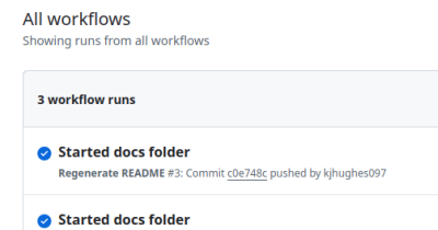
As part of documenting the process of developing this Virtual Disk Lib I wanted to have some docs in the repo that I could use to cover the steps. So I wanted to have a docs folder where I could ha...

A few months ago I was working on some VHD and VHDX file format conversions (because Azure Disks can only be created from ‘Fixed VHD’ format disks). There were/are a few challenges to this, so I th...

After having left Barracuda earlier this month I finally have a bit of time on my hands, so I thoght was about time I got around to migrating thias blog from Wordpress to a bunch of Markdown files ...
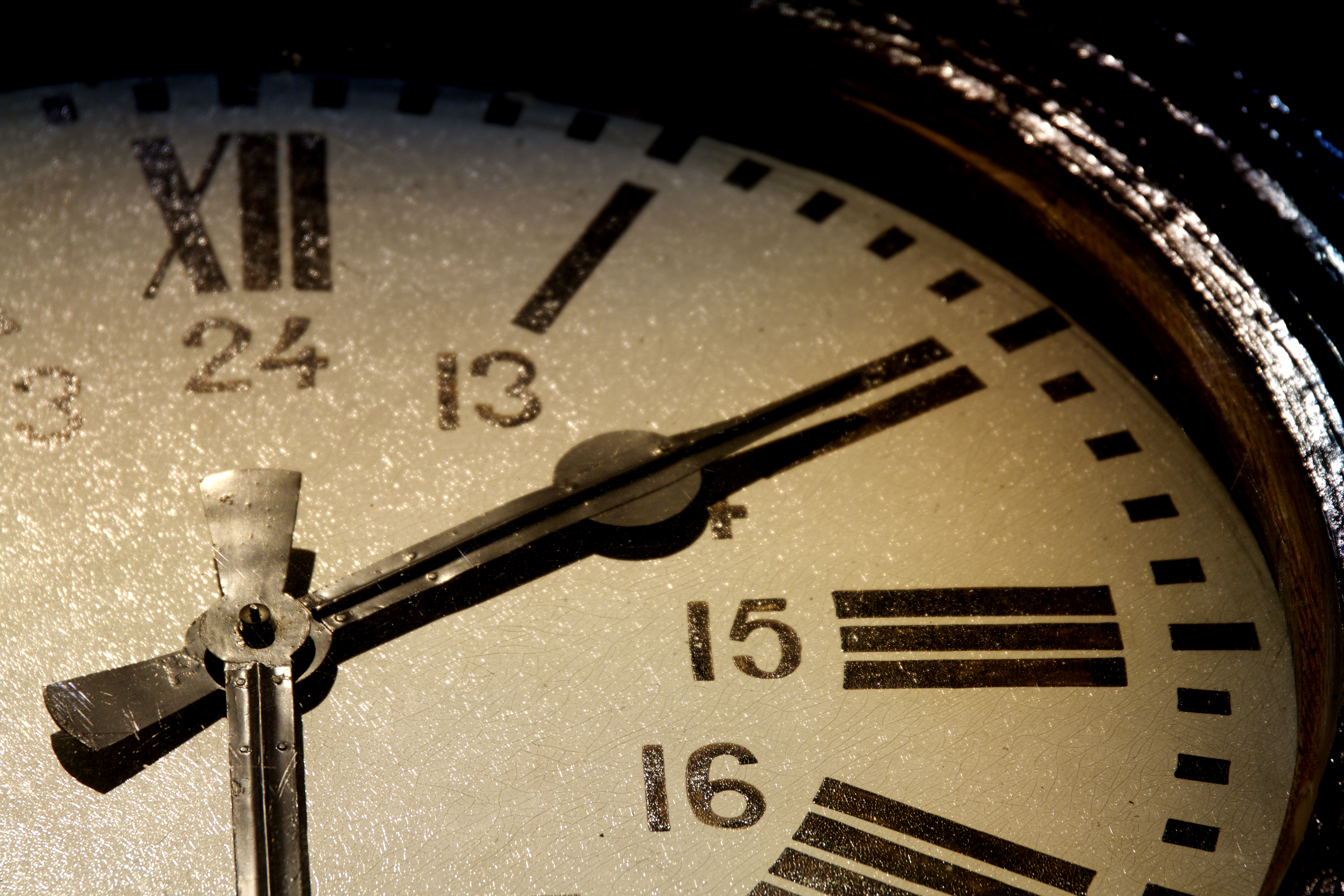
Wow!! 7 years since my last blog post. Time to rectify that…

So I had some (limited) success with my astrophotography last night. It was a clear night for an hour or so and I managed to get the settings for raspistill tweaked to capture some night stars. I g...
I’ve been looking at using my Raspberry Pi NoIR Camera for Astrophotography recently… A decent shot of the Milky Way is the objective. A decent time-lapse video of a clear sky through the night is...
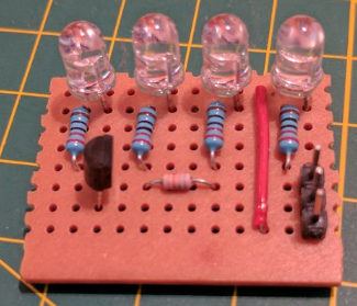
For a while now I’ve been meaning to put together a board with a few IR LEDs for a Pi NoIR Camera… The Pi NoIR camera is an add on for the Raspberry Pi that uses the CSI-2 camera interface on the ...
I’ve been playing around with getting a Raspberry Pi with a RDA5708 FM Radio module working. I bought 2 of them from ebay for around £7. They took around 2 weeks to arrive (from China). Wiring t...
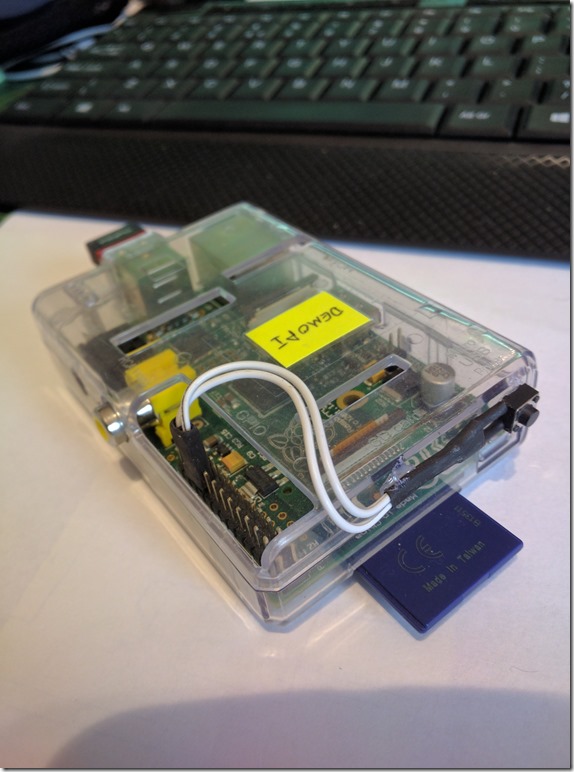
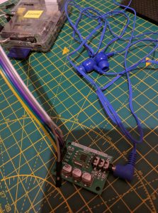
After one too many times of forgetting to shutdown my (headless) Raspberry Pi before shutting down my PC/laptop (and resorting to just pulling the power plug), I decided I needed a button to shut i...