I had a little SSD1306 128 x 64 bit OLED display laying around from a previous Arduino project, so I thought it was time to do a bit of OLED display interfacing with a Raspberry Pi.
Display
The device I had was an I2C version of the 0.96” 128x 64 bit SSD1306 OLED module. Monochrome only. These devices are available on Amazon for £3-£4 and make for a really interesting project. It’s only 4 wires to connect; 2 for I2C communications, and 2 for power (it can be powered from the +3.3v line on the Pi GPIO).

So, little jumper wires between 3.3v, Gnd, SDA and SCL on the GPIO header, and the device (all clearly labelled) and we are ready to start.
There are some libraries and tools available for this device from Adafruit. It is sometimes useful to begin with those, if nothing else than to make sure the device works, and you have it wired up right. However, we want to do this ourselves, so the first thing we’ll need is a copy of the data sheet to understand how the device works. Googling it, I found copies for download here, and here.
The bits we are interested in are section 8.7 Graphic Display Data RAM, and sections 9 and 10 (Command Table and Command Descriptions). It’s tough reading, but you can get there eventually.
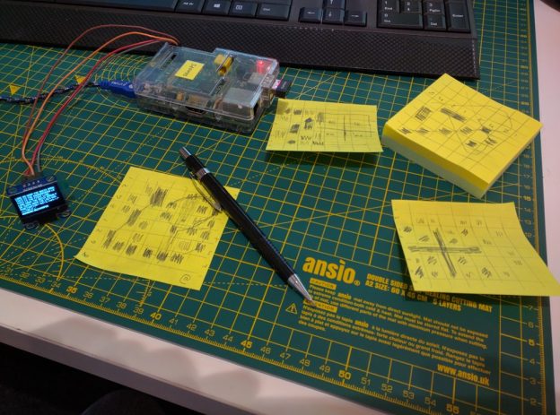
Essentially, we want to put it into Horizontal display mode so that we are writing one byte per column (128 columns per line), then moving down to the next line and writing the next set of bytes for this line of 128 columns. I’ve tried to explain this on a post-it…

OLED display interfacing with a Raspberry Pi – Software
Now that we have the device wired up and the datasheet downloaded it is time to write some code for OLED display interfacing with a Raspberry Pi.
I’ve tried to pull out all the ‘initialization’ commands and just lump them into an array – you can look them up in the data sheet if you want to understand this in a little more detail.
Here’s the sequence for init:
unsigned char initSequence[26] = {0x00,0xAE,0xA8,0x3F,0xD3,0x00,0x40,0xA1,0xC8,0xDA,0x12,0x81,0x7F,0xA4,0xA6,0xD5,0x80,0x8D,0x14,0xD9,0x22,0xD8,0x30,0x20,0x00,0xAF};
We also have to tell the display where we want to start the data being displayed from, in our case that is the top left. The command sequence for that is as follows:
unsigned char setFullRange[7] = {0x00,0x21,0x00,0x7F,0x22,0x00,0x07};
To get these commands sequences written to the device we need to send it over the I2C bus. Make sure your I2C is enabled (run sudo raspi-config). Here is the code we will use to send data over the I2C bus:
void writeI2C(unsigned char* data, int bytes) {
char *deviceName = (char*)”/dev/i2c-1″;
if ((i2cHandle = open(deviceName, O_RDWR)) < 0)
{
printf(“error opening I2C\n”);
}
else
{
if (ioctl(i2cHandle, I2C_SLAVE, i2cAddress) < 0)
{
printf(“Error at ioctl\n”);
}
else
{
write(i2cHandle, data, bytes);
}// Close the i2c device bus
char *deviceName = (char*)”dev/i2c-1″;
close(*deviceName);
}}
This simply opens the /dev/i2c-1 device, then gets a handle to our display device and writes data to it (and closes it afterwards).
When we have initialized the device we can then begin sending it data we want it to display. As you’ve seen above we just need to choose data bytes to send it that illuminate the pixels we want. For example sending 0xFF to every column (and page) will illuminate every pixel on the device. Sending 0x11 will produce 2 thin lines on each of the 8 pages (lines of characters).
That is great, but we want to send text characters to the device, how do we do that. Well the first thing we’ll need to do is to map out the characters and determine what bytes we will need to display them. Let’s start with ‘A’. You can see below that I have mapped this out over 4 bytes:

I’ve shaded in the pixels I want to illuminate to make the A character. The ‘Most Significant Bit’ (MSB) is on the bottom and the ‘Least Significant Bit’ (LSB) is at the top. You can see that I have also left the top line of pixels and the bottom line of pixels blank – this is to create a separation between each line of characters. The bytes we will need are 0x7E, 0x12, 0x12, 0x7E. We will also need to add a 0x40 byte before these to inform the display that we are sending some data to be displayed.
OLED display interfacing with a Raspberry Pi – Mini Sample App
So, if we initialize the display then send a sequence of these 5 bytes to it we’ll have the letter A displayed at the top left of the screen. Here’s the full code for an app that will display an A in the top left of the screen:
// Ken Hughes
// July 2016
#include <unistd.h>//Needed for I2C port
#include <fcntl.h>//Needed for I2C port
#include <sys/ioctl.h>//Needed for I2C port
#include <linux/i2c-dev.h>//Needed for I2C port
#include <stdio.h>
#include <string.h>
void writeI2C(unsigned char* data, int bytes) {
int i2cAddress = 0x3C;
int i2cHandle;char *deviceName = (char*)”/dev/i2c-1″;
if ((i2cHandle = open(deviceName, O_RDWR)) < 0) {
printf(“error opening I2C\n”);
}
else {
if (ioctl(i2cHandle, I2C_SLAVE, i2cAddress) < 0) {
printf(“Error at ioctl\n”);
}
else {
write(i2cHandle, data, bytes);
}// Close the i2c device bus
close(*deviceName);
}
}
int main() {// initialise the display
unsigned char initSequence[26] = {0x00,0xAE,0xA8,0x3F,0xD3,0x00,0x40,0xA1,0xC8,0xDA,0x12,0x81,0x7F,
0xA4,0xA6,0xD5,0x80,0x8D,0x14,0xD9,0x22,0xD8,0x30,0x20,0x00,0xAF};
writeI2C(initSequence, 26);// set the range we want to use (whole display)
unsigned char setFullRange[7] = {0x00,0x21,0x00,0x7F,0x22,0x00,0x07};
writeI2C(setFullRange,7);// send the letter A to the display
unsigned char letterA[5] = {0x40,0x7E,0x12,0x12,0x7E};
writeI2C(letterA,5);}
You can compile this code with the following command
gcc –o display-a display-a.cpp

OLED display interfacing with a Raspberry Pi – Full Character Set
Instead of adding the bytes for each letter multiple times we are going to create ourselves a ‘look up table’ – we want a letter H?, the code looks up H in a table and there it finds the bytes we need. This is a bit of a labourious process of working out the byte sequence for every letter (and number and punctuation character) and putting all of them into an ‘array of arrays’. It is slightly complicated further because we might have a different number of bytes for different letters. For example the ‘@’ sign needs 5 bytes whereas the letter I only needs 3. Not a problem, for each letter the first byte of the sequence will tell us how many bytes for the letter. For the case of our letter, it would look like this:
{4, 0x7E, 0x12, 0x12, 0x7e}, //A
The first byte is 4, telling us there are 4 bytes in the sequence to display the letter ‘A’. Here is the sequence for the ‘@’ sign, which requires 5 bytes.
{5, 0x7E, 0x42, 0x5A, 0x52, 0x5E}, // @
Fast forward through the section where I work out all the byte sequences and populated our ‘array of arrays’.

Now, we make sure our ‘array of arrays’ is laid out in the same sequence as the standard ASCII table. This allows us to implement a neat trick where if we subtract the ASCII value for ‘<SPACE>’ we get the correct offset into our array of arrays. So if the start of our data looks like this…
int fontData[][6] = {
{2,0×00,0x00}, // SPACE
{1,0x5E}, // !
{3,0×02,0x00,0x02}, // ”
{5,0×24,0x7E,0x24,0x7E,0x24}, // #
{5,0×44,0x4A,0x7E,0x52,0x22}, // $
{5,0×22,0x10,0x08,0x04,0x42}, // %
{5,0×34,0x4A,0x54,0x20,0x40}, // &
… and we want to display a ‘#’ character (ASCII value 35) then we subtract the ASCII value of ‘<SPACE>’ (which is 32) and get 3. Allowing us to look up the byte array at fontData[3] – which is {5, 0x24,0x7E,0x24,0x7E,0x24}
The first number (5) is the number of bytes we need to display this character, and the following 5 bytes are the actual values we send to the device to display this pattern.
OLED display interfacing with a Raspberry Pi – Bringing it all together
Now that we know how to get the correct bytes sequences we just need to pull everything together. This is a case of combining the initialization, the interpreting the desired characters into bytes sequences and the writing of the bytes to the display.
I found the easiest way to do this was to create a 128 byte array for each line…
unsigned char displayLines[8][128];
… and to set all bytes to zero to begin with …
for(int i=0; i<8; i++) {
for(int j=0; j<128; j++) {
displayLines[i][j] = 0;
}
}
Now, whenever we get text to display we begin filling up the 128 bytes of the current line …
c = toupper(c); // we only support UPPERCASE letters
int letterIdx = (c – ‘ ‘);
if(letterIdx > 64)
{
letterIdx = 65;
}int letterBytes = fontData[letterIdx][0];
for(int i=0; i<letterBytes; i++)
{
displayLines[currentLine][curr + i] = fontData[letterIdx][1 + i];
}displayLines[currentLine][curr + letterBytes++] = 0x00; // single byte space between letters
We also need to make sure that the remainder of the line is filled with zeros just in case we are overwriting a line that previously had text on it.
// now fill up any left over with 0x00s on the current line
while(currByteCount < 128)
{
displayLines[currentLine][currByteCount++] = 0x00;
}
Now that we have the displayLines arrays populated with the bytes we need it is a simple case of sending them to the device over I2C. We have to create a byte sequence that is a 0x40 (‘data stream coming’ command) followed by all the bytes for the line. We do this for each line…
unsigned char buffer[129] = {0};
buffer[0] = 0x40;
for(int i=0; i<128; i++) {
buffer[1 + i] = displayLines[line][i];
}
writeI2C(buffer, 129);
… and now we have working code that we can use to call a function with some text as the parameter and have that text displayed on the OLED screen.


Source Code
The full source for this OLED display interfacing with a Raspberry Pi project can be found on github at : https://github.com/kjhughes097/pi-ssd1306-oled
This separates out the functionality into a ‘SSD1306’ class that you can use in other apps. It also separates the character mapping header (charmap.h) out so that it is easy to add additional characters (you could try adding lowercase letters ?).
The ‘sample’ app, display-a.cpp is self contained and shows the basic use of I2C to send data to the display. The other ‘sample’ app, oled.cpp shows how to use the class. The makefile will compile the oled app – at the command line simply type
make
Hope this has been useful. Please leave a comment below if you thought so.