Windows Live Writer is currently being a real pain for me. I have my ‘My Documents’ redirected to a network drive in our UK office (where I usually work), but I am currently in our Westboro, MA office so my ‘My Documents’ is now effectively on the end of an interoffice VPN.
This seems to be causing all manner of issues with Windows Live Writer (using Process Monitor I can see it doing file reads / updates every second or so for all the recent posts and draft posts – horrible). It hangs for minutes at a time (and causes Outlook to hang during this period also) – in summary it’s unusable (when I’m connected to our corporate network, when I’m disconnected it’s fine)…
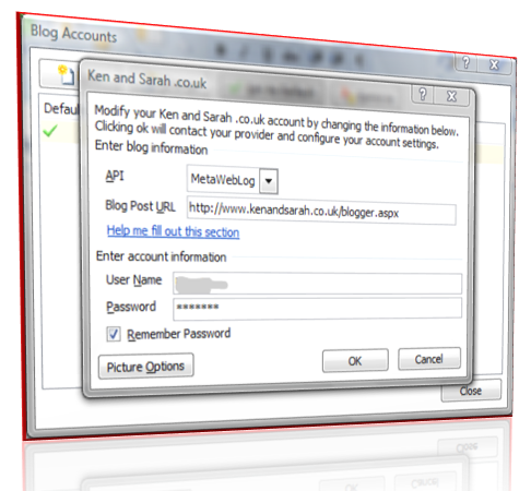
So, I’ve been looking at blogging from Word 2007 – I’ve actually only just found that it can do it (whilst looking for the Save As menu). Just set up my account details – very simple…
The insert picture options and other formatting options are excellent (at least in Word they are, let’s see how it turns out on the website). The picture to the left (there should be one) should have a kind of 3D perspective (similar to the new Aero Tab Switching in Vista)
Category insertion is a bit long-winded, I need to click ‘Insert Category’ and then choose from a drop down – so multiple categories takes a bit of time… Still, it does find all my existing categories and allows me to define others.
OK, fingers crossed, let’s see how things when published…
UPDATED:
Unfortunately it didn’t work !! Word could not handle uploading images to the metaWebLog API implemented in dasBlog – strange because Windows Live Writer handles it just fine. That’s a real pain as the image formating options in Word 2007 are stunning. Here is the that should have gotten posted first time (and inline) above (added manually).
Ken,
I’ve been trying to get Word 2007 to work with dasBlog for a few weeks now (since the RTM was made available on MSDN). The only documentation I could find on it were some old beta2 posts about the date formatting. Your site (and the screenshot) helped me get it working. Thanks.
I was able to get the images working too by using an ftp directory. This is what I had to do on Windows Live Writer. I put a screenshot on my site.
http://www.wroolie.co.uk/PermaLink,guid,16a0ac28-7ca1-4230-b657-154b71d2a504.aspx
Hopefully, people who’ve had the troube we’ve had will be able to find our posts and get their Word posting working. I like WLW, but it seems irrelevent when you have the full office suite.