For a while now I’ve been meaning to put together a board with a few IR LEDs for a Pi NoIR Camera…
The Pi NoIR camera is an add on for the Raspberry Pi that uses the CSI-2 camera interface on the Pi. It’s just like a normal camera except it has no IR filter (hence NoIR).
This means it can capture in the IR range as well as the visible light range of the spectrum. This is good for dark or nighttime shots where you can ‘light up’ the scene with IR light (that is not visible to the human eye) instead of ‘normal’ visible (white) light.
The Pi NoIR Camera itself does not come with any IR light source. So for nighttime photography is pretty useless on it’s own.
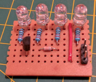
The IR LEDs for a Pi NoIR Camera circuit is pretty simple to build. A few IR LEDs (I got some from Amazon that draw about 20mA and drop somewhere between 1.2 to 1.4 volts) and some resistors. Each LED needs it’s own current limiting resistor (this question gives a good explanation of why). You could just run the LEDs and resistors from a +5v and ground connection directly. However I wanted the LEDs to be switchable by a GPIO pin. As I planned to use 4 LEDs I’d need to be switching ~80mA so I’d need a transistor. The transistor would be driven from a GPIO pin so I’d need a resistor there too.
The circuit I put together look like this:
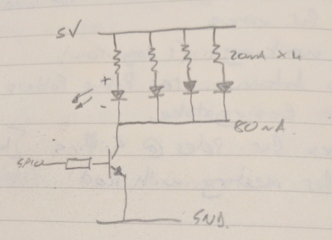
Calculating the resistor values was pretty easy.
IR LED current limiting resistors
We know the LEDs draw up to 20mA (0.02 A) and drop between 1.2 and 1.4 volts. We want to drive them close to 20mA to get maximum brightness from them.
5v – 1.3v (average) = 3.7v / 0.02 A = 185 Ohms. So I selected 220 Ohms to be on the safe side.
Transistor base resistor
We want the current on the base to be limited to a reasonable value so that we’re not pulling too much from the GPIO pin.
With an HFE of around 100, a 2N2222 only needs about 1mA to drive 100mA through the load. I may add more LEDs in the future, so I opted for something that would give me ~4mA at the base.
3.3v – 0.6v = 2.7v / 0.004 A = 675 Ohms. So I opted for 560 Ohms which will give around 4.8mA.
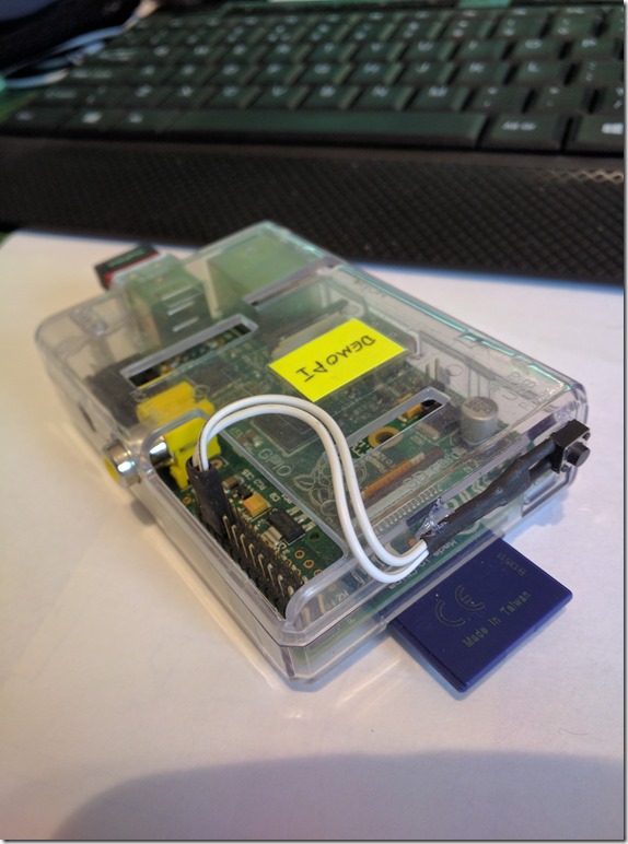
I soldered this all up on some veroboard with 3 header pins to connect up the +5v, Gnd and GPIO pin:
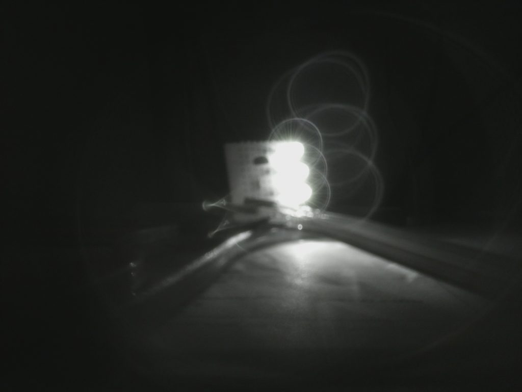
Next, I connected it up to my Raspberry Pi (GPIO pin 23) and set that GPIO to an output and high. Switched off the lights. Took a raspistill image on my other Pi (with the NoIR camera connected) and you can see it works :
So, the little IR LEDs for a Pi NoIR Camera project was completed in an hour or so. Next up will be something a bit more complex (for me) – trying some outdoor, nighttime photography…